
Fixturing and Routing of Plastics with CNC
Once the proper router bit has been selected for a plastic machining application, productivity depends heavily on programming methods, part fixturing, spindle speed, and feed rate.
With the increasing use of routers to machine plastics, there has been a leap forward in the design of tooling capable of producing high-quality finishes on a variety of products. High-speed steel, carbide-tipped, and solid carbide tools are available in a wide range of geometries and sizes to rout most plastics.
Programming Techniques
The goals of routing wood and routing plastics are similar: high-quality finishes at fast feed rates. Many programming techniques used in wood routing will therefore work well in plastics.
The primary difference in plastic routing is the ability of cut chips to re-weld themselves to the finished surface. In softer plastics this can occur frequently and lead to poor edge finish. Preventing this re-welding while maintaining fast feed rates is one of the keys to productive plastics machining.

Reduce Tool Dwell
The key to preventing chips from re-welding is simple: keep them cool. One of the easiest methods is maintaining a fast feed rate. Due to programming limitations, however, this is not always practical.
Most routers have acceleration, deceleration, and curve-speed limitations when cutting radii and corners. Dead stops should be avoided whenever possible. When cutting outside corners, the router may stop and dwell while changing directions.
One solution is “exit ramp” programming. By programming corners as outside loops, the tool is not allowed to dwell while still producing a square corner.
Ramp Into Inside Cuts
Another common dwell condition occurs during the initial plunge of an inside cut. As the bit bores into the material, it continually re-contacts the cut surface. Unless the bit is a spiral or has shear, chips may not be evacuated efficiently.
“Ramp in” cutting can reduce this effect by gradually plunging the bit on the Z-axis as it begins forward travel on the X- or Y-axis. If required, the bit can travel backward after reaching full depth to remove the remaining ramp.
When boring a dedicated hole, it can also be advantageous to rout the hole rather than plunge directly. A small-diameter bit can ramp into the hole in a circular fashion and use routing action to cut it to size. This can help maintain tight tolerances and reduce underside blow-out when the plug is ejected.
Roughing and Finishing Passes
If chip re-welding remains a problem after removing dwell points, moving from high-speed steel tooling to solid carbide may allow an increase in feed rate and further reduce heat.
On thicker plastics, a rough-cut and finishing-pass combination can improve finished edge quality. Leaving approximately 0.080 inch on the edge with a roughing tool allows the finishing tool to remove enough material to remain stable and resist chatter.
The more durable roughing tool absorbs most of the wear, while the finishing tool can produce more pieces before requiring replacement.
Climb vs. Conventional Cutting
When cutting nested or mirrored parts with a single pass, surface finish can vary depending on whether the tool is presented to the material in a climb-cut or conventional-cut configuration.
Generally, conventional cutting yields a better edge. When a separate finish pass is used, however, the second pass can be a climb cut. If nested cutting creates finish problems, the cut can also be completed in two passes with a smaller-diameter tool, reversing tool travel to finish each exposed edge.
Tool Oscillation
When cutting laminated plastics or materials with an abrasive layer, tool oscillation can greatly increase tool life. Materials such as plastic laminated with aluminum can create a severe wear line on carbide and high-speed steel tooling.
By oscillating the tool vertically along the Z-axis during the cut, wear can be spread over a larger portion of the cutting edge.
Fixturing
Quality production demands quality material, quality tooling, and quality fixturing. Fixturing must be solid and reliable. Poor hold-down can lead to reduced edge quality, shortened tool life, or broken tools.

Vacuum Hold-Down
Vacuum hold-down is one of the most prevalent methods in CNC routing, but the system must be designed properly. A basic piece of MDF with weather-stripping tape and a few drilled holes is not sufficient for demanding routing applications.
Using the router to create a grid connecting the vacuum ports allows vacuum to reach the edges of the part being machined. This increases holding power and can improve edge finish by creating a more rigid setup.
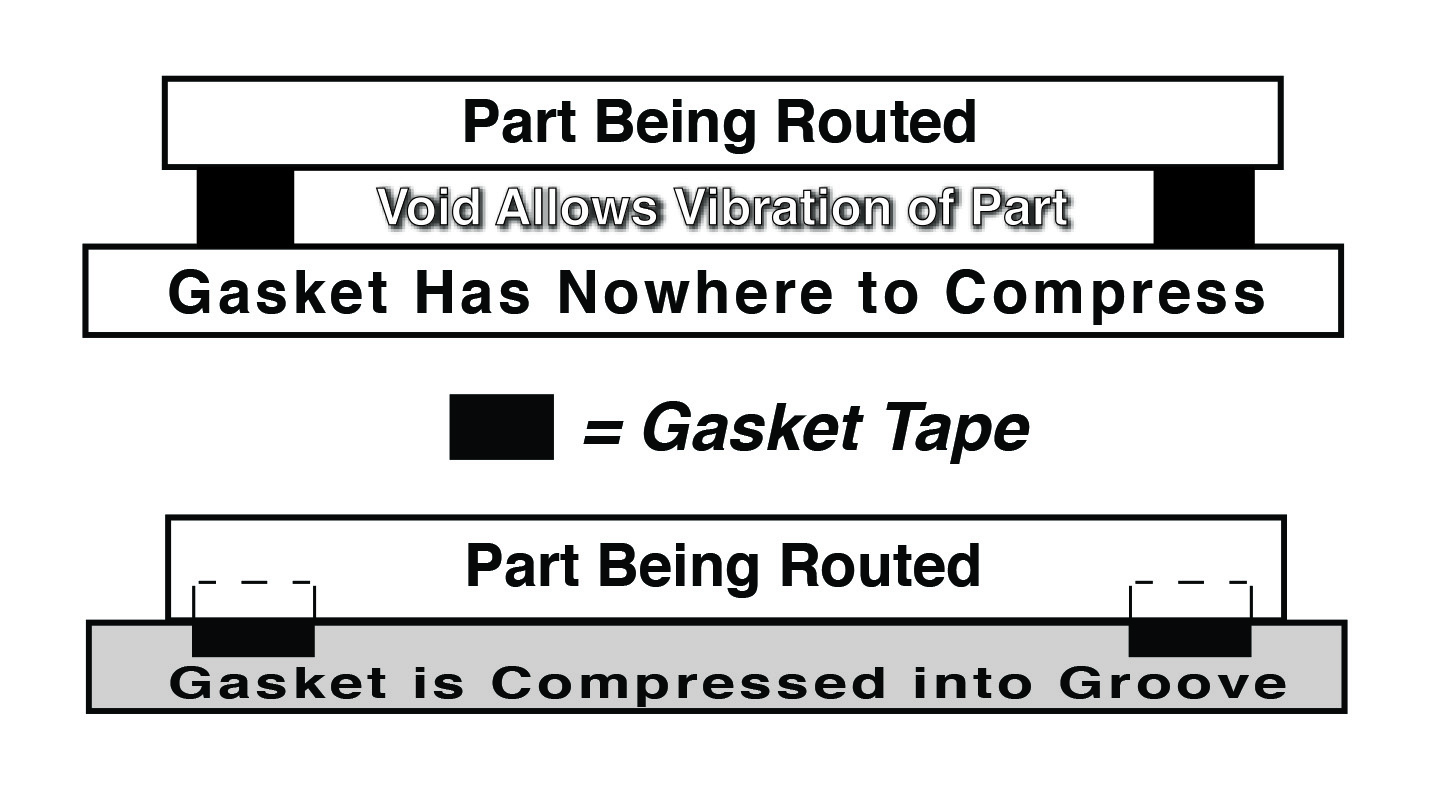
Proper gasketing tape should also be installed in an oversized channel. Tape with excessive “memory” may fail to recover after repeated compression, allowing vacuum to bleed away. If the channel is too narrow, compressed tape may prevent the part from fully contacting the vacuum surface and allow vibration to occur.
Dedicated Spoilboards
Dedicated spoilboards can improve safety and holding performance for particular parts. Small scrap pieces can become loose when they are too small to be held effectively by vacuum pressure, allowing them to chatter on the table, contact the router bit, or be thrown from the cutting area.
One solution is to build up selected areas of the spoilboard so the part is held on a pedestal or plateau. Excess material can then fall to the main spoilboard after being cut, keeping it away from the cutting tool.
Dedicated spoilboards are also useful when material composition requires a downcut spiral or shear tool. By routing channels below the cutting path, chips are given a place to evacuate instead of being trapped in the cut.
If these configurations still do not provide sufficient holding force, parts can be secured with riveted tabs or screws placed through scrap portions. This is generally a last resort because setup time increases and throughput decreases.
Speeds and Feeds
If the part is fixtured securely and the correct tool has been selected, spindle speed and feed rate become major factors in finished part quality.
Speeds and feeds can vary considerably depending on router horsepower, tooling, and material composition. The defining relationship between speed and feed is chipload.
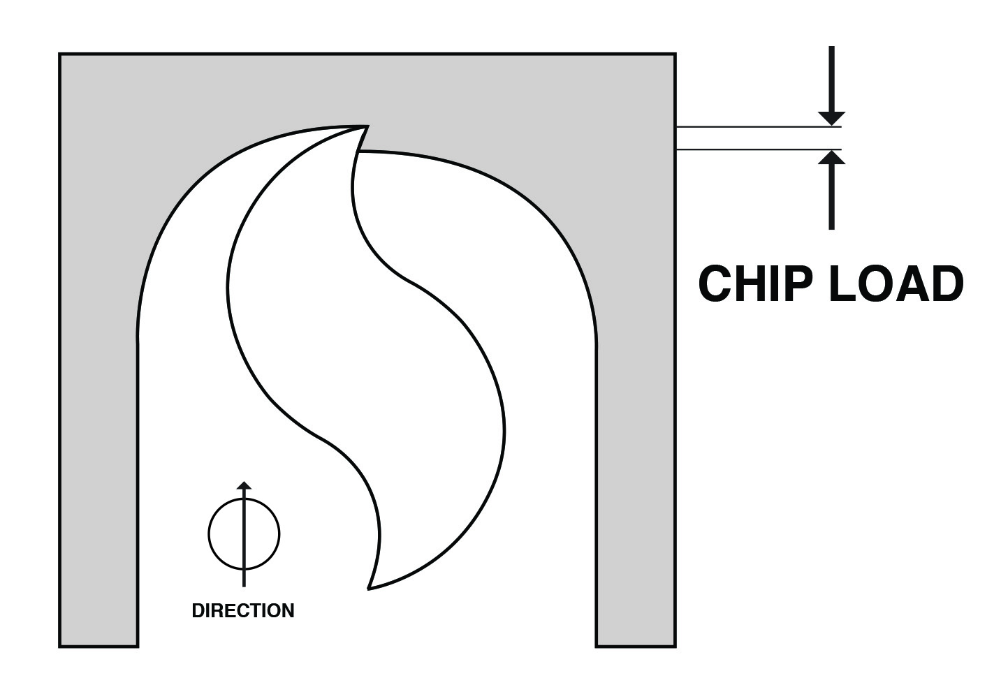
Increasing chipload causes a larger chip to be removed. A larger chip removes more heat from the cut, which can extend tool life.
The primary means of increasing chipload is to increase feed rate, which also increases parts produced per hour. Chipload can also be increased by reducing spindle speed when feed rate is already at its maximum.
A decreased chipload means the cutting edge is presented to the workpiece more frequently. Because every cutting edge has a finite useful life, the highest chipload that still produces an acceptable finish should generally be used.
Typical Starting Points
Using a spindle speed of approximately 18,000 RPM as a reference, solid carbide spiral tools designed specifically for soft plastics can be run at approximately 300 inches per minute. Solid carbide O-flutes should also be run at relatively high feed rates to clear chips efficiently.
If finish begins to degrade, spindle speed can be increased while maintaining the same production rate. High-speed steel O-flute tools generally require slower feed rates to reduce bit deflection, chatter, and knife marks.
Harder plastics work well with low-helix tools designed to break plastic chips away cleanly. These tools can run around 300 inches per minute. Double-edge V-flute tools may run from approximately 125 to 250 inches per minute depending on tool style and composition.
Fiber-Reinforced Plastics
Fiber-reinforced plastics behave differently because materials such as fiberglass, aramid, and carbon fiber compounds do not form chips in the same manner as conventional plastics.
In these applications, the bit should generally be run as fast as practical. The cooler the tool remains after machining, the longer its expected life.
Forced-Air Cooling
If adjusting speeds and feeds still produces a hot tool or occasional chip re-welding, forced air can be used to improve chip evacuation.
First ensure the dust collection system is operating efficiently. Air directed through a nozzle can then clear chips from the cutting area. Venturi-effect nozzles can also lower the temperature of the air charge while providing additional cooling and chip evacuation.
Putting It All Together
With the increasing number of plastic formulations in the marketplace, there will continue to be a need for high-quality machining and finishing.
After proper bit selection, successful routing depends heavily on optimum programming techniques, solid fixturing, and appropriate speeds and feeds. Tooling, fixturing, and programming deserve the same attention as the CNC equipment performing the work.