
The Most Common Problems in Plastic Routing
The diversity of plastic materials in the industry today makes it almost impossible to avoid some kind of machining problem. Material differences, combined with a wide range of applications, can serve as a precursor for routing problems.
Before tackling the most common problems, a few basic premises should be reviewed.
All Plastic Is Not Created Equal
Many times, a user will know the trade or generic name of a plastic being routed, but will fail to recognize there are physical properties of the material germane to the machining process.
Even a change in color can alter the way a plastic material reacts to a cutting tool.
As a beginning point for machining and tool selection, plastic can be categorized as either soft or hard plastic. This can be determined by the flexibility or rigidity of the material or the type of chip it produces in the routing process.
Sometimes there can be soft and hard plastic characteristics within a generic plastic group. For instance, cast acrylic is classified as a hard plastic, while extruded acrylic falls on the softer side. They require different tooling considerations because of the way they machine in the routing process.
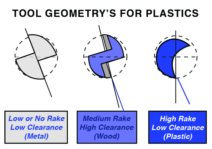
Cutting Tool Geometry Is Paramount
With the diversity of plastic in mind, it is equally important to acknowledge router tool geometry as a key to success.
Through years of testing, tools specifically toleranced for plastic routing have been developed for hand-fed as well as CNC applications. The common denominator in the success of these router tools is the presence of high rake and low clearance in the geometry of the tool.
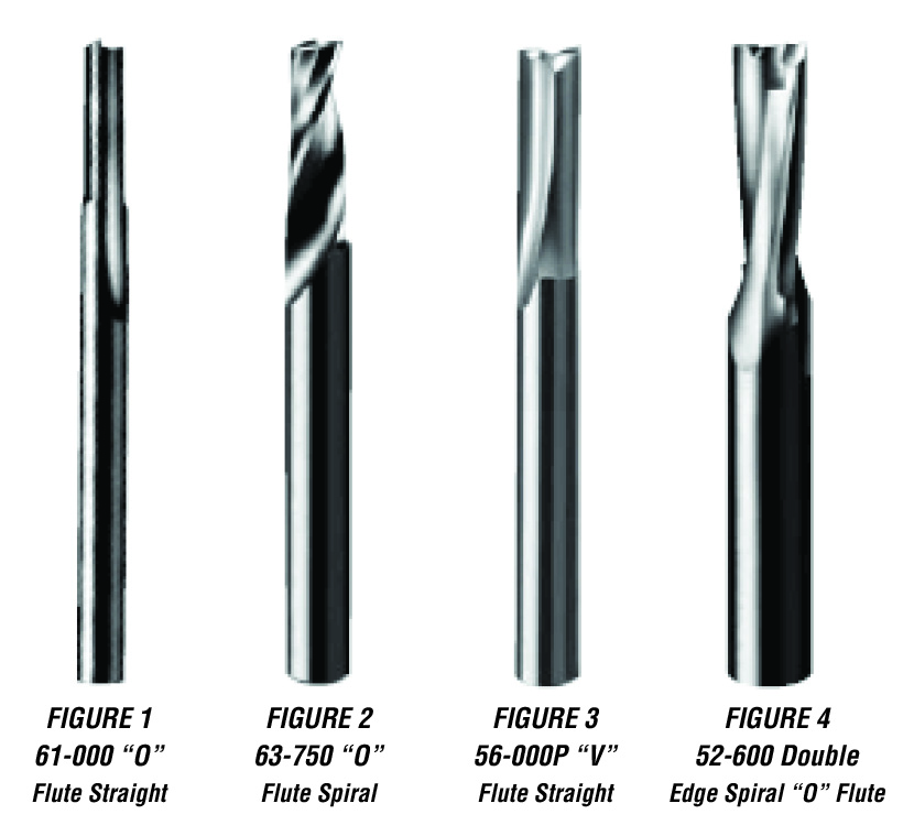
Soft plastic utilizes O-flute router tools in straight or spiral configurations. Hard plastic tools may use V-flute straight tooling or O-flute spiral tooling with hard-geometry considerations.
The decision regarding straight or spiral tooling hinges upon the direction the user wants to influence the chip or part. Straight tooling has a neutral effect, while spiral tooling can move chips in an upward or downward direction.
Welding of Plastic Material
Welding of chip during the routing of plastic parts is probably the most irritating problem encountered in the industry. It is costly in terms of time and scrap rate, but is also avoidable.
Besides inappropriate tool selection, chip welding can occur because of improper chipload, small tool diameter size, influencing the chip improperly, or the direction of the cut.
Plastic is extremely sensitive to heat, and the act of routing at high feed and spindle speed rates creates a warm cutting environment.
Chipload is the thickness of the chip and is determined by feed rate, spindle speed, and the number of cutting edges in the router tool. The chip is the mechanism by which heat is transferred away from the tool and the part.
Chipload = Feed Rate ÷ (RPM × Number of Cutting Edges)
The goal in plastic routing is to produce an adequately sized chip to remove heat while still meeting finish requirements.
In small parts where feed rate is limited, spindle speed can be adjusted to maximize chipload.
Small-diameter tools can also cause welding because of limited chip-clearance capability.
Tool geometry must also influence the chip in the correct direction. For example, using a downcut spiral in a blind slot can cause chips to be recut and welded.
Direction of cut may also contribute to the problem. In most cases, conventional cutting direction is recommended.
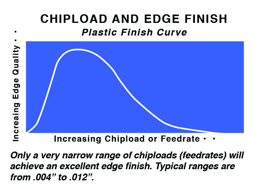
Poor Finish
Surface finish is one of the most important considerations in plastic routing, particularly for signs, exhibits, and point-of-purchase displays where the finished edge remains visible.
As with all plastic routing applications, selection of the proper tool is essential to good edge finish. Finish is also heavily influenced by chipload.
Besides chipload, other areas of concern include improperly holding parts and the condition of the CNC machine itself.
CNC routers commonly use dedicated or flow-through vacuum spoilboard systems. Poorly designed spoilboard systems can lead to inadequate part hold-down and unacceptable finish.
The condition of the machine and tool-holding system is also critical. Even the correct cutting tool will not perform properly if the machine and collet system are not maintained.
The tool must run concentrically to function at optimum levels. Excessive runout can deteriorate finish and increase scrap.
Resources
This information provides a starting point for identifying and correcting common plastic-routing problems.
Additional technical resources can include plastics material manufacturers, suppliers, CNC machinery manufacturers, and technical article archives.
The problems of welding and poor finish can often be addressed by understanding the material, selecting router tooling with plastic-specific geometry, applying proper chipload, maintaining rigid part hold-down, and keeping the router and collet system in good condition.